Showing posts with label mobile hardware. Show all posts

Wednesday, March 15, 2017

Samsung I9505 Galaxy S4 insert sim solution Done 100% Working

Samsung I9505 Galaxy S4 insert sim solution 100% Working

Here i am sharing this information because it is a best and 100% working Samsung I9505 Galaxy S4 Insert Sim solution. if you are also facing the same problem so please try and do not forget to give comment your success story .

Samsung I9505 Galaxy S4 insert sim solution 

Just remove the nfc ic and then short two part make a jumper simple .
Samsung I9505 Galaxy S4 insert sim solution
NOTE - This solution is checked by us but in case of any problem or issue we are not responsilble for that. USE THIS AT YOUR OWN RISK 

Monday, June 4, 2012

Thursday, May 31, 2012

How to Repair Cellphone Not Charging, No Reponse, Charger Not Supported Problem Issues

There are few types of charging problem issues like Not Charging, No Charging Response and Charger Not Supported.
A problem issues with "Not Charging" shows on a display when a charger is being plug-in, this problem occurs when a required current or voltage is not enough to boost up  and charge the mobile phones battery.
One reason of this problem is  a faulty BSI Line, a BSI line is a Battery Size Indicator that tell the charging control circuit how's the batteries working status.


not%20charging%20response

The battery has a BSI output indicator terminal that connected to its negatives terminal with  desired value of resistor on it.


battery Bsi


One other charging problem issues is the No charging response when a battery charger is being plug-in, it stays no response or nothing happens.
One reason of this is a faulty protection circuit section. this happens when there is no voltage reach to charging circuit indicators and controls. If the protection circuit breakdown this will result to "charging no response" situation. You need to check each components for short and open circuits. You may start from the fuse then to the coil and the diode.

Charger Not Supported problem is cause by a faulty BTEMP thermistor component, BTEMP stands for Battery Temperature, This is the one that monitors the battery temperature status during at charging status, if this one having a problem , it wont allow any charger to proceed to charging stage.
This all, is only a brief explanation of how charging problem issues occurs, while charging the mobile phones .
There are lots of ways on how to troubleshoot each and every kind of handsets. Hope at least, this one let help you understand how charging problem issues occurs, and by this you can gain ideas to move into a stage where you can practice how to troubleshoot this kind of issues.

Wednesday, May 30, 2012

SMD Capacitor

The types of capacitor which is commonly used in small space circuit like the cellphone uses the Tantalum type of capacitor, 
Tantalum capacitors are used in smaller electronic devices including portable telephones, pagers, personal computers, and automotive electronics.
It also offer smaller size and lower leakage than standard. .
There are two types of Capacitors used in Mobile Phones Circuits,
The Polarized and Non-Polarized Capacitors.
This are the Capacitors may look like  that are being used in mobile phones circuit.


SMD

The Polarized Capacitor 
Tantalum Capacitors which is polarized, and may be used in DC circuits. Typical values range form 0.1uF to 470uF.
Standard Tantalum values change in multiples of 10, 22, 33, and 47. Normal Temperature Coefficient [TC] for Tantalum Capacitors is +5%.
Polarized capacitors are typically used in large voltage situations, such as DC line filtering to reduce noise related to uneven voltage levels after rectification from an AC source. Mainly measured in microfarads. Polarity is critical to these devices. They are marked with the voltage rating (usually double the circuit voltage used) as well as the farad marking. 

Non-Polarized Capacitor
Non-polarized are similar to polarized except the plates are similar metal. 

Polarized caps are typically used in large voltage situations, such as DC line filtering to reduce noise related to uneven voltage levels after rectification from an AC source. Mainly measured in microfarads. Polarity is critical to these devices. They are marked with the voltage rating (usually double the circuit voltage used) as well as the farad marking. 

non-polarized caps are typically used in low voltage situations, both AC and DC. Polarity is not critical. Measured in pico farads typically. 
Decimal multiplier prefixes are in common use to simplify and shorten the notations of quantities such as component values.
Capacitance, for example, is measured in Farads, but the Farad is far too large a unit to be of practical use in most cases. For convenience, we use sub-multiples to save a lot of figures. For example, instead of writing 0.000000000001 Farads, we write 1pF (1 picofarad).
The more common prefixes and the relationships to one another are as follows.
Abbrev.PrefixMultiply byor
ppico0.00000000000110-12
nnano0.00000000110-9
µmicro0.00000110-6
mmilli0.00110-3
-UNIT1100
kkilo1000103
Mmega1000000106
Units
1000 pico units=1 nano unit
1000 nano units=1 micro unit
1000 micro units=1 milli unit
1000 milli units=1 unit
1000 units=1 kilo unit
1000 kilo units=1 mega unit

Tolerance

All components differ from their marked value by some amount. Tolerance specifies the maximum allowed deviation from the specified value. Tolerances are normally expressed as a percentage of the nominal value.
For example, a component with a marked value of 100 and a tolerance of 5% could actually be any value between 5% below the marked value (95) and 5% above the marked value (105).

posts Blackberry bold 9000 keypad ways solutions


This morning I shared trick jumpers to problems keypad on blackberry bold 9000, probably from one of the readers of this blog, is currently experiencing problems the keypad on the blackberry bold 9000, on a phone keypad damage usually occurs on hardware factors, there are some phones have a problem of damage keypad is caused by software, but it was only a few phones and not all of them caused by damage to the software and not all of them caused by hardware, but this time that I share is the destruction of the keypad on the blackberry bold 9000 caused by hardware, ie, if there is one lane keypad the end, you can do with jumpers according that you see in the image above

How to Check Basic Electronic Components Using a Multi-Meter


How to Check Basic Electronic Components Using a Multi-Meter 

Basic electronic components such as resistors, capacitors, diodes and transistors are widely used in any electronic devices and gadgets. Knowing how to conduct a test on this components using a multimeter would give you an idea on how to trouble shoot and repair any defective cellphones or electronic equipments at home. Below are some basic D.I.Y. regarding proper testing of this components using a multimeter.


How to Check Resistors?

Read the indicated  code value indicated in Schematic Diagram then select the Ohm-scale within but not way below the indicated value. A resistor is good if its resistance is close to the indicated value.Tolerance should be considered with the ohmmeter reading. While, no resistance reading at all on the ohmmeter scale settings means that the resistor is open. A zero resistance reading on all ohmmeter scale settings means that the resistor is shorted. 
Photobucket

How to Check Capacitors?


In most cases, a capacitor fails due to the deterioration of the dielectric material between its plate.Defective capacitors can have an internal shorted terminals, excessive leakage and degradation of capacitance meter. For an electrolytic capacitor (capacitors with polarity), short the terminal capacitor to discharge it prior to testing.

To test a capacitor, set the multimeter to Rx10 or Rx1K scale. Connect the tester negative probe to the capacitor positive terminal and the positive probe to the negative terminal. 
Photobucket
A good indication for electrolytic capacitor shows the meter needle deflecting towards zero and moves back again to infinite resistance position. 
For ceramic, Mylar and other capacitor with a capacitance with less than 1.0 uF, the meter will not deflect at all. 
Photobucket
A defective indication for an electrolytic capacitor shows that the meter will rest on zero and remain stationary at a point which is an indication that the capacitor is shorted.

How to Check Diodes?


Set the multimeter knob to any of the resistance position (x1, x10, x1K or 10K ohm ).Connect the positive probe to the anode and the negative probe to the cathode.Then connect the positive probe to the cathode and the
negative probe to the anode of the diode. A good indication in the first procedure will show the meter deflected very little or may not deflect at all.
Photobucket
And in the second procedure, the meter will deflect towards zero.The actual resistance reading is the forward resistance of the diode. 
Photobucket
A defective indication shows that the meter won't deflect at all even when the probes are reversed. Or the meter deflects at the same time or almost the same resistance reading for both steps.


How to Check Transistors:


Bipolar transistors are usually checked out of a circuit by means of an ohmmeter. When it is desired to check for the resistance across the transistor emitter and collector, NPN or PNP, ohmmeter probes may be connected either way. A good transistor will show above a reading above 1000 ohm.

How to determine if it is NPN or PNP transistor?

To determine the correct terminal of the transistors, set the range selector to x 1 or 10 ohm.Connect the positive probe to the emitter and the negative probe to the base of the transistor. Note the reading interchange the connection of the probes to the leads of the transistor.

Base your conclusion on the table:

POSITIVE PROBE TO: -----NEGATIVE PROBE TO: -----RESISTANCE READING-- CONCLUSION:
  Emitter------- --   Base---------- Less than 150 ohm ------Transistor is NPN
 Base --------------Emitter --------Infinity ----------------Transistor is NPN
Photobucket

POSITIVE PROBE TO:  NEGATIVE PROBE TO:   RESISTANCE READING:    CONCLUSION:  
-Emitter------------Base ---------Infinity   ----------------  Transistor is PNP
Base --------------- Emitter --- - Less than 150 ohm -------  Transistor is PNP
Photobucket
Some defective indications of transistors: Resistance between any pair of the terminals is less than 10 ohms, means that the transistor is shorted. Resistance between base and emitter or base collector for both the forward and reverse application of ohmmeter probes is infinity (meter needle don't deflect), means that the transistor is open. Transistors overheats (except power transistors) during normal operating condition means that the transistor is shorted.

 How to Check an LED ( Light Emitting Diode)

Set the Muti-meter to x1 connect the positive probe to cathode and the negative probe to anode. The good and working LED will then light up or glow, a busted LED will not.
Photobucket

How to Check a Coil?

Set the multimeter to X1 a good and working coil have a reading approximately point to zero ohms, without any reading means the coil is open or busted.
Photobucket

How to Check a Fuse?

A blown SMD Fuse is not visible to our eye, just set the multi-meter to x1 and put both test probe to both end side of the fuse. A full reading here to zero or continuity check is full. without any reading means the fuse is already busted.
Photobucket

How to Check IC chips (Integrated Circuits)?

IC Chips is hard to determine faulty by using only a multi-meter, some advance equipment like the one that the manufacturer used during their productions. However; you can determine a faulty chips by some few experiences when it comes to troubleshooting, One techniques is that by comparing two same components from one another. like for example; if one chips is suspected to be faulty, then by replacing it with a good and working same chips, you can now determine it if the said chips got a problem. It is a trial and error method at first; but as long as your experience and knowledge skills increases, you can determine it more quickly and accurately.
Further, we will tackle this issues and give you some tips and tricks.

Soldering and Desoldering Tools


Soldering Iron
A soldering iron is a tool normally used for applying heat to two or more adjoining metal parts such that solder may melt and flow between those parts, binding them securely, conductively and hermetically.
A soldering iron is composed of a heated metal tip and an insulated handle. Heating is often achieved electrically, by passing an electrical current (supplied through an electrical cord or battery cables) through the resistive material of a heating element. Another heating method includes combustion of a suitable gas, which can either be delivered through a tank mounted on the iron (flameless), or through an external flame.
Some soldering irons heat up and cool down in a few seconds, while others may take several minutes.Soldering LEAD
 Soldering lead is used to bond or connect electronic components. 
Solder is a fusible metal alloy with a melting point or melting range of 90 to 450 degree Celsius (190 to 840 °F), used in a process called soldering where it is melted to join metallic surfaces. It is especially useful in electronics . Alloys that melt between 180 and 190 °C (360 and 370 °F) are the most commonly used. By definition, using alloys with melting point above 450 °C (840 °F) is called brazing. Solder can contain lead and/or flux but in many applications solder is now lead free.


While it is possible to do some wiring without soldering connections, soldering is the preferred approach. Proper soldering is easy with the right tools and techniques. One item that is critical is the right solder. DO NOT use the environmentally friendly lead free solders, they don't work worth a damn. Even in carefully controlled industrial conditions, lead free solders produce inferior connections. As much as the politicians backed by environmentalists would like to, they can't legislate metallurgy.
Soldering Paste
Solder paste (or solder cream) is used for connecting the terminations of integrated chip packages with land patterns on the printed circuit board. The paste is applied to the lands by printing the solder using a stencil, while other methods like screening and dispensing are also used. A majority of defects in mount assemblies are caused due to the issues in printing process or due to defects in the solder paste. An electronics manufacturer needs to have a good idea about the printing process, specifically the paste characteristics, to avoid reworking costs on the assemblies.


Characteristics of the paste, like viscosity and flux levels, need to be monitored periodically by performing in-house tests.
Soldering flux Soldering flux is just a safe, convenient acid for dissolving the oxide skin off the metal
you want your solder to wet well. Also dissolves oxide off the liquid solder, making it
less crusty and therefore more shiny.


"Acid" flux is the stronger class of flux; it has something like hydrochloric acid in
it. (The paste form has zinc chloride.)
This is good for making difficult oxides dissolve so difficult metals like stainless
steel can be solder-wetted.
But the acid can hang around later trying to corrode the metal it just cleaned for you.
So for electronic stuff we mostly do not use it.
If we do, we scrub it off with things like toothbrush, water, soap, alcohol, baking soda,
to minimize acid residues.

The flux built into most solder wire is called rosin flux.
I think it is an organic acid (so is vinegar, and tart-tasting "citric acid"),
stuck onto larger molecules that melt only at soldering temperatures.
That is the clear yellow-brownish plaque that sits on the solder's surface when you are
done.
It does the same stuff as acid flux, but it is milder two ways.
It is only strong enough to reduce weakly oxidizable metals like copper, tin, lead,
silver.
So it is just strong enough for electronics use, but not for soldering to stainless
steel or iron or anything with chrome or aluminum.
And rosin-flux goes back to its plastic-like solid form after use, so it does not act
very corrosive to the metals later on.
So we do not need to clean it away carefully.
It can be cleaned away if you want to work at it, with brush-scrubbing and the right
"polar solvents".
"Flux remover" is sold in spray-cans for this. Rubbing alcohol with a dash of dish-soap
sort of works for me.
Try it and see what it looks like.


 Soldering Wick
A solder wick (also desoldering wick or desoldering braid) is a tool for removing solder from any solder joint. Usually, it is a roll of fine, braided 18 to 42 AWG wire, typically oxygen free copper, which has been treated with a rosin solder flux.


Close up to a piece of solder wick


Close up to the netting of a solder wick


To remove solder with it, one presses the wick onto the solder joint to be removed and then heats the wick portion that is on the connection with the tip of a soldering iron. As the rosin melts onto the wick and the connection and the solder reaches its melting point the solder rushes via capillary action onto the clean copper braid. Once everything has melted and the solder fuses with the braided copper, the wick is lifted along with the solder and is then cut off and disposed of

ways to improve insert sim motorola L6 & L7


Insert the SIM in Motorola extremely rare, but precisely because it rarely happens will be very difficult solution we can, because rarely are experiencing this, therefore I provide for you who need this jumper trick

Thursday, May 17, 2012

What is An Application Processor in Mobile Phones Circuit Do

https://blogger.googleusercontent.com/img/b/R29vZ2xl/AVvXsEjjWv6o-aRuo6FkCRj9dD9bDftZ9In_cNB2gVJCfUUOneEJjHZHvH4cn_y-MXz8A04gH6xbRrabBb2FweGukdyzR86I4RKoeZMm-vsgjPrLzPutsUKmQNYvSY7ZDYwiIbZ6_Gw_Y0kB7EI/s1600/application+processor.jpg
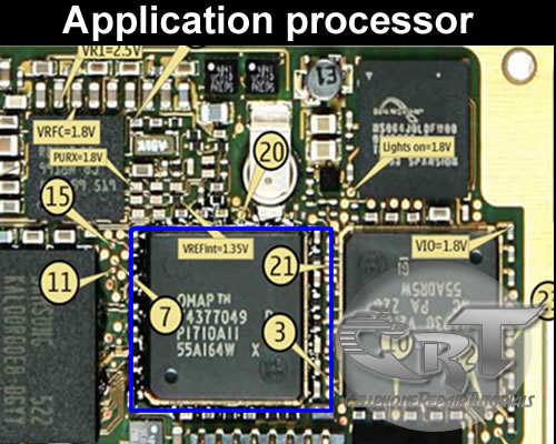
An application processor is a central proccessing unit (CPU) like the one installed on personal computer. It is the brain and controls all kind of data and information any application in mobile phones circuit.
It is microprocessor integrated circuit (IC) chip.

https://blogger.googleusercontent.com/img/b/R29vZ2xl/AVvXsEg7Q2u7tPEyt-A6cYVF9vMllCt3UPvel1kly7gvjx6V_jd1QEVFT4lFMALXbYMkg-kSvQU4dkcUAdodakV_I6ETXyjGj1VColjaXKjRGo_hkMGRvHcgpHKMDRnKXoo_CaoEjuDrJTjY98A/s1600/n95-3j.jpg

 LCD controller, camera interface, serial interfaces, memory interface,USB  controller, bluetooth and wifi controller,and more. are controlled by an the application processor.

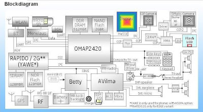
Here's an example of an application processor block diagram below, on how this kind of IC works on mobile phones circuit. This kind of  an application is commonly used on Nokia latest designed of mobile handsets. The description of this application processor below will help us understand how does this certain IC work.
omap block diagram
omap block diagram
OMAP2420 Processor

The OMAP2420 processor is a single-chip applications processor that supports all cellular standards, and complements any modem or chipset and any air interface. It is intended for high-volume wireless handset manufacturers and is not available through distributors. The OMAP2420 includes the benefits of the OMAP 2 architecture’s parallel processing, giving users the ability to instantly run applications and operate multiple functions simultaneously without quality of service compromises. The OMAP2420 includes an integrated ARM1136 processor (330 MHz), a TI TMS320C55x™DSP (220 MHz), 2D/3D graphics accelerator, imaging and video accelerator, high-performance system interconnects and industry-standard peripherals.
Graphics

The OMAP2420 processor embeds Imagination Technologies' POWERVR MBX™ graphics core, making it the first applications processor to support OpenGL ES® 1.1 and OpenVG™, providing superior graphics performance and advanced user interface capabilities. TI is enabling sophisticated and dynamic images with "smart pixel" technology offered via OpenGL ES 1.1. This unique technology allows each pixel in an image to be programmed individually, giving developers the power to create rich effects with cinematic realism. Users will now experience "life-like" facial features, advanced reflection effects and multi-textured backgrounds in the mobile environment.

Multimedia enhancements made in the OMAP2420 include an added imaging and video accelerator for higher-resolution still capture applications, multi-megapixel cameras and full-motion video encode and decode with VGA resolution of 30 frames per second. An added TV video output supports connections to television displays for displaying images and video captured from the handset. 5-Mb internal SRAM also boost streaming media performance. Access to the OMAP Developer Network also provides an extensive range of programs and media components that manufacturers can use for differentiating and delivering products to market fast.
Key Features:

    Dedicated 2D/3D graphics accelerator at 2 million polygons per second
    Added imaging and video accelerator enables high-resolution still image capture, larger screen sizes and higher video frame rates
    Supports high-end features including 4+ megapixel cameras, VGA-quality video, high-end interactive gaming functionality and analog/digital TV video output
    5-Mb internal SRAM boosts streaming media performance
    Software compatibility with previous OMAP processors
    Parallel processing ensures no interruptions or degradation of service with simultaneously running applications
    Optimized power management companion chip, TWL92230 12 mm x 12 mm, 325-ball MicroStar BGA™, 0.5-mm pitch

How does Charging Circuit Works from a Battery Charger to charge a Mobile phone Battery


This lesson is also important for charging problem troubleshooting for knowing which parts or components has being used to make a charging circuit. Many mobile phone technicians had been asking me,how does mobile phone charging circuit works? How does a battery charger can charge a mobile phone battery?
To tell the truth many of them has never heard of this even they already fix thousands of mobile phones in their years of cellphone repair careers." and I am one of them.
I don't know but I know how fix it, its so easy"  that's what we've oftenly  said.
Well, we all know that all  mobile phones  are all battery operated handsets that needs to charge the battery so that it will continue working,  failure to charge it will result to unable to power up the mobile phone handsets.
Here's a brief explanation of how charging circuit works,
 I prepare this simple idea and diminished some electronics technical terms so that everyone without adequate knowledge on electronics technical terms might can catch up with this.

A  charging circuit is composed of the following stages or sections. 

1. 
Battery Charger Circuits - Although this is not found on mobile phones PC board circuit and have separate circuit but definitely  this is also part of charging circuit; without this, the charging circuit is not complete and will not work completely.   
This circuit is all parts and components  that being mounted on any mobile phone charger, this is the one that converts 
AC (Alternating Current)voltage to DC  (Direct Current)voltage.What is AC Voltage? This voltage is a power source that we used in our household appliances to work  and operate, this voltage can cause risk of electric shock and very dangerous to humans when being touch.This kind of voltage hasan alternate polarity.
What is DC voltage? This voltage is a low level voltage which typically found on any kind of  batteries.
This kind of voltage have two polarities, the negative and the positive. 

Here's how the battery charger works, the 110 or 220 AC volts  coming from the electrical outlet at home or etc. will be converted to a desired DC voltage like 4.5 to 6 volt DC because the phone only accepts and can be operated into small amount of DC voltage.


A DC voltage output of a charger is only an artificial DC voltage, why is that? because only a battery cell can produce a 100% pure DC voltage.

2. 
Protection Circuit- this circuit is composed of a Fuse, Inductor coil Diode and Capacitors,  before the DC voltage reach to the charging voltage control circuits the protection circuit is the one that control and check if that  voltage is in exact amount. Let say the desired amount of DC voltage is only 5.6 volts above that point the fuse will be blown out to stop the voltage to flow so that it prevents damaging to another corresponding circuits.
In a protection circuit below of Nokia BB5 mobile phones a diode is the one that measure the amount of voltage from the battery charger, this diode has a reaching point of desired voltage to measure of how much amount of voltage will be allowed to flow within that line, when exceed to that desired point of voltage the diode will then cut it off.
 like for example if that diode is being designed that only allows only 7 volts from the battery charger to flow on that line. Now, above that desired voltage let say that the voltage becomes 8 or higher the diode will then be reacts and destruct itself, this is what then so-called shorted component; so that the current will flow directly to ground and will not reach to the following or corresponding circuit. If the diode will cut off or shorted the fuse will tends to blow and totally cut the voltage line. The inductor coil's role is to filter unwanted voltage saturation, it rejects abnormal voltage modulation caused by electrostatic interference.

3. 
Charger Voltage Control Circuit - This is the stage where the charger voltage and current is being stabilized, amplified, rectified, regulated and other voltage purification process is being held in this area before it feeds to the battery. This kind of circuit commonly being pack in a chips together with another circuits.  

A failure of this certain area will result on charging problem status. This area mostly called by most technician as a 
Charging IC it is because this circuit is inside in a particular IC chips, but eventually  this circuit also accompanied by many other circuit types and not exclusive to a certain charging area.
This pictures shows is the next corresponding circuit from the protection circuit area. The voltage from charger is now then feeds into  three  terminal inputs of the charger voltage control circuits.
in this figure shows  after the voltage stabilization and purification process the voltage is now then feeds to the battery terminal.

4.
 Charging Control Circuit - this is the area where the charging process is being monitored, this is the one that sends information to  the application processor to start or stop  the charging process. This area is part of  Power management circuit, so-called POWER IC by many technicians.
In this picture  that there are two terminal signal from the voltage  control  that sends data to the Charging control circuit, this two data signals  will inform to the charging control circuit that a charger voltage is being  entered or plug-in. After this charging control circuits receives the data it will then analyze and convert that data into digital signal then sends it to the Application processor. 

The application processor which is the brain of all the circuits now then decide if all the data's are in correct or in right information to begin the process,
It always relies on the data that sends by the charging control circuit, then  decide all data and completely process it.


Okay now lets take an example and apply this particular method on a mobile phone circuitry component layout, I have here a Nokia N95 board, which is a good way to start with, while we still working on advance training.  Now, try to analyze and compare all of those previous picture above and combined them into each corresponding stages or section, in this manner you can build an step by step tracing procedure on how to deal charging problem issues.
In the picture above shows, how and where the voltage flow from a charger voltage source through the entire  PC board circuit. This is the the method where you can start and manage how to locate and trace each and every component to find possible problems regarding charging problem issues.

How to Test Mobile Phone Vibration Motor

A mobile phone vibration is created by a small motor called Vibra motor. when applied by a voltage or current it rotates and the vibration is generated by a small tiny piece of metal attach to its tip.

Mobile phone vibrator motor

Checking this small piece of motor was so very easy just set the analog multi-tester range to X1 in resistance
 settings then connect the both probes to each terminals, polarity doesn't matter here for the motor will rotate clockwise if its in the right polarity. and rotates counter clockwise when not in each corresponding polarity.
A good and working vibration motor will then rotate and a bad or busted one will not.

computer science course online | computer science degree syllabus | computer science help online | computer science learn online | computer science lectures online | computer science online course | cs final subjects | cs online school | degree computer | degree in programming | free computer classes online | free online computer classes | intro to computer science online | learn computer science online | learn computer science online free | mit computer science online | msc computer science online | online bachelor in computer science | online bachelor of computer science | online bsc computer science | online computer classes | online computer classes free | online computer coding classes | online computer coding courses | online masters cs | online ms in cs | online msc computer science | online projects for computer science students | programming degree | teach computer science online | what is computer science degree

Labels

brand new desktop computers
cheap refurbished laptops
computer desktop packages
computer discount
desktop computer new
desktop computer package deals
desktop computer packages
desktop pc package deals
desktop pc packages
discount computer parts
discount computers
discount desktop computers
discount laptop computers
laptop computer sales
laptop computers for sale
laptop sale
laptops for sale
new computer desktop
new desktop
new desktop computer
new desktop computer with windows 7
new desktop pc
new pc desktop
new windows 7 desktop computers
pc desktop package
refurbished computers
refurbished desktop computers
refurbished laptops
refurbished notebooks
refurbished pc
used laptop for sale